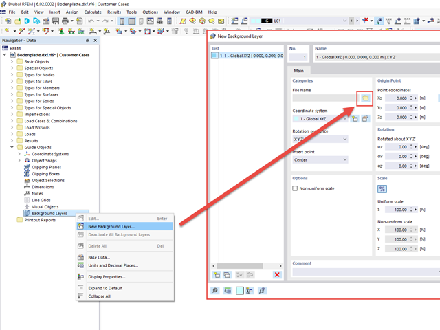
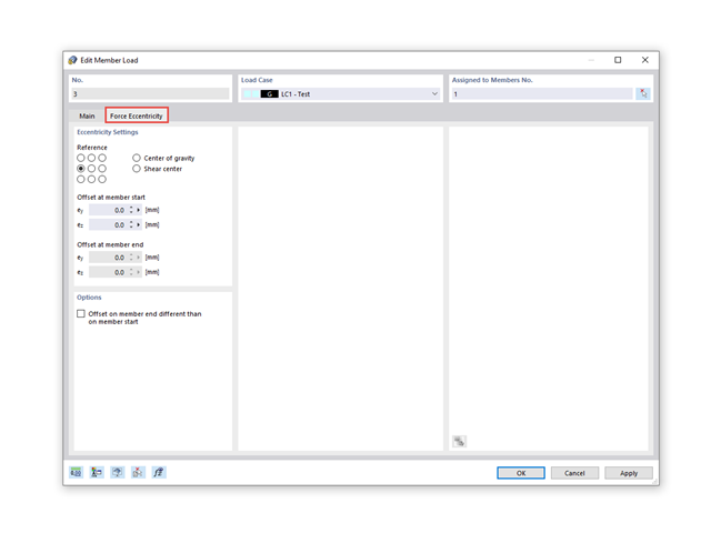
I would like to convert the load from a surface load to a line load; that is, to apply it to the individual beams. How can I do this without using an auxiliary area?
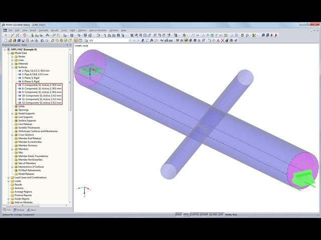
I used the method of intersections to create an opening in a circular cylindrical wall surface.How can I hide these auxiliary surfaces to create an intersection?
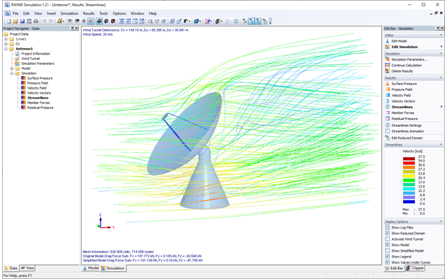
To what extent are the results of the RWIND Simulation calculation compatible with the valid wind standards (for example, EN 1991‑1‑4, ASCE/SEI 7, and others)?
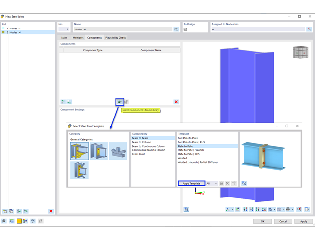
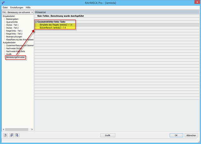
What does the design information mean: Geometry error left side: End plate of the girder: Lambda2 >1.4 Column flange: Lambda2 >1.4 I cannot find an explanation in the manual or online.
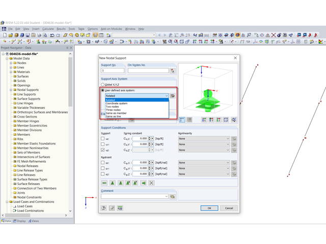
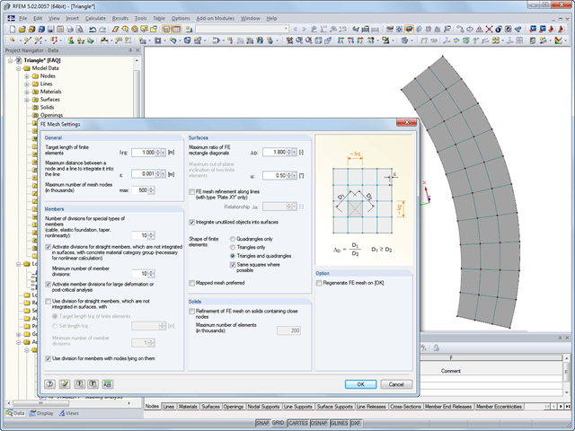
Is it possible to align the FE mesh manually in RFEM?In my example, there are "rigid" triangular elements at the edge, where quadrangular elements would be more realistic.